
Prerequisites
Read these first if vertex/fragment shaders, rasterization, or clip space are new.
- OpenGL ES overview — why Android games/UI effects use GLES
- Rendering Pipeline Overview (Khronos) — stages from vertices to pixels
- LearnOpenGL — Hello Triangle — minimal shader + draw path
- Vertex Shader / Fragment Shader — per-vertex vs per-pixel work
Why the pipeline map matters
OpenGL turns vertex and index buffers into pixels through a short chain of stages. Treat each stage as a contract, and “mystery” bugs get local: wrong pose → vertex stage, missing faces → assembly, FPS cliff → fragment/fill, flicker → depth. Wrong pixels are rarely “the GPU is broken” — they are usually data that violated one stage’s contract.
If you already know Android UI or systems work and only skimmed OpenGL/ES, you do not need another glossary. You need somewhere to point when the screen is wrong, and a habit of naming the stage before changing random GL state. That same vocabulary carries into systems work: in Rushmore, the hard question is not only how fragments are shaded, but which world may write which display path before pixels hit the panel.
Pipeline overview
OpenGL-managed memory usually starts with two arrays:
- Vertex array — positions (and attributes) that become screen-space points, triangles, fragments, then colors
- Element (index) array — which vertices form triangles; order matters
Joe’s modern OpenGL intro (credited in References) fits the whole path in one figure:
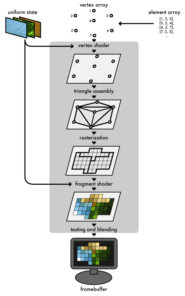
Figure 1. Pipeline overview — vertex/element inputs, programmable stages, framebuffer output.
Desktop pipelines can also insert optional tessellation and geometry stages between the vertex shader and the rasterizer. Mobile GLES 2/3 — the more common target for app engineers debugging a phone build — usually skips both, so this map sticks to the stages you will actually hit in that world.
Vertex shader — geometry that “moves”
The GPU reads each selected vertex. The vertex shader projects it (typically into clip space) and may emit varyings — color, UVs — for later interpolation.
When the mesh loads and the silhouette looks familiar but sits off-camera or paper-thin, skip the fragment shader. Check model/view/projection, attribute stride, or a forgotten homogeneous w first. That bug almost never starts in rasterization.
#version 330 core
layout (location = 0) in vec3 aPos;
uniform mat4 uMVP;

void main() {
  // why: clip-space position is the contract for later stages
  gl_Position = uMVP * vec4(aPos, 1.0);
}
Triangle assembly — connectivity bugs look random
Projected vertices become triangles as independent triples, a strip (reuse last two vertices), or a fan (first vertex + later pairs):
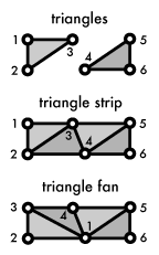
Figure 2. Triangle assembly modes.
Faces that disappear or twist after you “just” change draw mode usually live here. One index drives all attributes — you cannot index positions and UVs independently. If holes appear after switching GL_TRIANGLES ↔ strip, blame assembly before the fragment shader.
Winding order compounds this: OpenGL treats counter-clockwise as front-facing by default, and back-face culling silently drops any triangle wound the other way. If a mesh renders fine with GL_CULL_FACE disabled but vanishes (or shows only its inside faces) once you enable it, you flipped a normal or imported geometry with inconsistent winding — that is an assembly/culling bug, not a rasterizer or lighting one.
Rasterization — triangles become fragments
Each triangle is clipped, then broken into pixel-sized fragments. Vertex outputs are interpolated across the surface:

Figure 3. Rasterization produces fragments for the fragment shader.
A few thousand triangles with collapsing FPS when the camera fills the screen is often fill rate, not vertex count — especially on mobile. A full-screen quad with a heavy shader can out-cost a denser mesh that covers fewer pixels. Measure before “optimizing the mesh.”
Fragment shader — the usual performance villain
For each fragment, the fragment shader decides color (textures, lighting, effects). It runs per covered pixel, which is why it dominates cost for many real apps.
Smooth until you turn the camera? You just covered more pixels or more layers. Transparent UI over 3D and naive multi-pass effects tax this stage hard on phones.
Alpha blending adds a second failure mode that looks like a shader bug but is not: unsorted transparent draws blend in whatever order the CPU submitted them, so overlapping glass, particles, or UI panels can render with the wrong surface “winning” even though every fragment shader is individually correct. Sort transparent geometry back-to-front (or use an order-independent technique) before you start rewriting blend math.
#version 330 core
in vec2 vUV;
uniform sampler2D uTex;
out vec4 FragColor;

void main() {
  // why: keep this cheap — it may run millions of times per frame
  FragColor = texture(uTex, vUV);
}
Frame buffer — depth and stencil are product features
Before a fragment sticks, tests filter it into color, depth, and stencil buffers.
| Buffer | Job |
|---|---|
| Color | What you see |
| Depth | Occlusion (farther fragments discarded) |
| Stencil | Mask drawable regions |
Z-fighting between coplanar surfaces, or a HUD that vanishes behind geometry, is a depth/draw-order problem — disable depth for overlays on purpose. Stencil shows up when you need a hard mask (portal, mirror region, UI punch-through): draw the shape into the stencil buffer first, then constrain later color writes to that mask.
References
- Figures from Joe’s An intro to modern OpenGL — Chapter 1: The Graphics Pipeline (duriansoftware.com)
- Site: Rushmore
- OpenGL ES spec (Khronos) — mobile GLES vs desktop GL when a stage “works on the laptop”